- Top Results
- Bosch Sensortec Community
- Discuss
- MEMS sensors forum
- Re: BMA400: noise performance, falsely activity detection interrupts.
BMA400: noise performance, falsely activity detection interrupts.
- Subscribe to RSS Feed
- Mark Topic as New
- Mark Topic as Read
- Float this Topic for Current User
- Bookmark
- Subscribe
- Mute
- Printer Friendly Page
- Mark as New
- Bookmark
- Subscribe
- Mute
- Subscribe to RSS Feed
- Permalink
- Report Inappropriate Content
07-07-2020 07:51 PM
BMA400 datasheet only provides rms noise for +/-4g range. What about 8 and 16g ranges?
I am using normal mode, 8g range, 200Hz sampling rate and x2 oversampling (osr=2), 24mg hysteresis, xyz,
Sensor is steady-state, no vibration. But once in a while I am getting falsely activity detection interrupts.
Trying to figure out whether it is because of noise, or noise + some slight vibration.
Solved! Go to Solution.
- Mark as New
- Bookmark
- Subscribe
- Mute
- Subscribe to RSS Feed
- Permalink
- Report Inappropriate Content
07-07-2020 10:03 PM
Hi,
Thanks for your inquiry.
BMA400 has typical noise density of 180ug/rt(Hz) on x/y axis and 240ug/rt(Hz) on z axis under the condition of +/-4g full scale range and OSR=3. The rms noise level in the unit of mg is related to the ODR and OSR. The table on page 21 of BMA400 datasheet defines the rms noise at different ODR and OSR. The noise density and rms noise level are not related to full scale range. So at +/-8g and +/-16g full scale ranges the noise desnsity and rms noise level are almost the same as the values at +/-4g full scale range.
Please let us know how you configure BMA400 interrupt so that we can try to duplicate the issue.
Thanks.
- Mark as New
- Bookmark
- Subscribe
- Mute
- Subscribe to RSS Feed
- Permalink
- Report Inappropriate Content
07-08-2020 02:28 AM - edited 07-08-2020 02:34 AM
Thanks for the response and explanation. It does make sense to me.
1. Accelerometer and Interrupt configuration:
REG_ACC_CONFIG1: +/-8g, OSR = 2, ODR = 200Hz.
REG_ACC_CONFIG2: use acc_filt1 data source.
REG_ACC_CONFIG0: normal power mode.
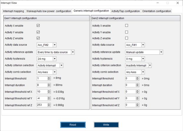
GEN1INT_CONFIG0: enable XYZ, use acc_filt2 (100Hz output datarate), update reference everytime, 24mg hysteresis, OR all axes.
GEN1INT_CONFIG2: threshold 8mg/LSB.
GEN1INT_CONFIG3 and _CONFIG31: 8 ODR ticks.
REG_INT_CONFIG0: generic 1 interrupt enable.
REG_INT_CONFIG1: latch interrupts.
REG_INT1_MAP: map generic 1 interrupt.
REG_INT2_MAP, REG_INT12_MAP: no other interrupts mapped.
REG_INT12_IOCTRL: active low interrupt.
In ISR: read STATUS and REG_INT_STAT0, check for gen1_int_stat bit.
2. It is sufficient to sligthly tap on table where PCBA with BMA400 is, to cause interrupt to occur multiple times. For instance, during 500ms window, I observe 1-10 events even without intentionally tapping. Sometimes it is 0, as expected.
I am not working in vibration-insulated environment, but I would not expect such a high sensitivity. It seems like IC "internal" noise + some light external disturbance is causing that.
3. I found that this issue is more prominent with 3.3V Vdd (and VDDIO). With 1.8V Vdd this happens much-much less frequently. However, Vdd should not affect the noise performance that much, correct? Is it possible for noisy 3.3V VDD to cause such an issue?
4. Increasing threshold to >40mg/LSB and/or min event duration to >16 ticks resolves the issue. But again: on my other device with 1.8V VDD all works almost perfect without this adjustment.
- Mark as New
- Bookmark
- Subscribe
- Mute
- Subscribe to RSS Feed
- Permalink
- Report Inappropriate Content
07-09-2020 12:56 AM
Hi,
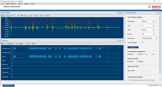
Thanks for the detailed description. I used our APP2.0 base board and BMA400 shuttle board and DD2.0 GUI SW to test your settings. It works as expected. The VDD of BMA400 is 3.3V.
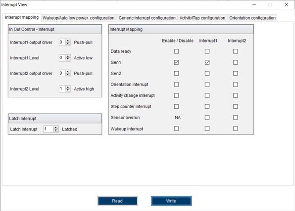
BMA400 Gen1 interrupt is mapped to INT1 pin with push-pull and active-low as shown below.
Gen1 configurations are as shown below the same as yours.
When I place the boards on the desk with no motion, Gen1 signal stays low while INT1 signal stays high. When I tap the boards, I can see many pulses on INT1 pin the same as yours. This is because INT is latched and when you read status register every time in ISR, INT pin will be cleared. If you don't read status, then INT pin will stay low all the time which means that the interrupt is latched. In order to reduce the number of pulses, you may do some tasks inside ISR or outside ISR after you see the Gen1 interrupt on INT pin. Then you may add delay of 100ms for example. Finally you can read status register to clear the latched INT1 signal.
To sum up, BMA400 noise level is not related to 3.3V or 1.8V, +/-4g or +/-8g, +/-16g. You can fine tune the threshold and duration values to adjust the sensitivities to motion detection.
Thanks.
Still looking for something?
- Top Results


