- Top Results
- Bosch Sensortec Community
- Discuss
- MEMS sensors forum
- BMI090L synchronisation
BMI090L synchronisation
- Subscribe to RSS Feed
- Mark Topic as New
- Mark Topic as Read
- Float this Topic for Current User
- Bookmark
- Subscribe
- Mute
- Printer Friendly Page
- Mark as New
- Bookmark
- Subscribe
- Mute
- Subscribe to RSS Feed
- Permalink
- Report Inappropriate Content
08-16-2020 03:14 PM - edited 08-16-2020 03:40 PM
The Github repository includes example code to configure synchronisation but there is no documentation for the theory of operation or required electrical connections. I have therefore had to infer this missing information through reverse engineering.
Please can you confirm that my following description is correct.
Theory of operation
An accelerometer interrupt pin can be configured as an input and used to trigger an accelerometer sample each time an interrupt is detected. The gyroscope can be configured to sample continuously at a fixed rate and to generate an interrupt each time gyroscope data is ready. Connecting the gyroscope interrupt output pin to the accelerometer interrupt input pin will result in the accelerometer sampling each time gyroscope data is ready. Thus synchronisation is achieved.
Implementation
The following code is copied from synchronisation example on Github.
/*set accel interrupt pin configuration*/
/*configure host data ready interrupt */
int_config.accel_int_config_1.int_channel = BMI090L_INT_CHANNEL_1;
int_config.accel_int_config_1.int_type = BMI090L_ACCEL_SYNC_INPUT;
int_config.accel_int_config_1.int_pin_cfg.output_mode = BMI090L_INT_MODE_PUSH_PULL;
int_config.accel_int_config_1.int_pin_cfg.lvl = BMI090L_INT_ACTIVE_HIGH;
int_config.accel_int_config_1.int_pin_cfg.enable_int_pin = BMI090L_ENABLE;

/*configure Accel syncronization input interrupt pin */
int_config.accel_int_config_2.int_channel = BMI090L_INT_CHANNEL_2;
int_config.accel_int_config_2.int_type = BMI090L_ACCEL_SYNC_DATA_RDY_INT;
int_config.accel_int_config_2.int_pin_cfg.output_mode = BMI090L_INT_MODE_PUSH_PULL;
int_config.accel_int_config_2.int_pin_cfg.lvl = BMI090L_INT_ACTIVE_HIGH;
int_config.accel_int_config_2.int_pin_cfg.enable_int_pin = BMI090L_ENABLE;

/*set gyro interrupt pin configuration*/
int_config.gyro_int_config_1.int_channel = BMI090L_INT_CHANNEL_3;
int_config.gyro_int_config_1.int_type = BMI090L_GYRO_DATA_RDY_INT;
int_config.gyro_int_config_1.int_pin_cfg.enable_int_pin = BMI090L_ENABLE;
int_config.gyro_int_config_1.int_pin_cfg.lvl = BMI090L_INT_ACTIVE_HIGH;
int_config.gyro_int_config_1.int_pin_cfg.output_mode = BMI090L_INT_MODE_PUSH_PULL;

int_config.gyro_int_config_2.int_channel = BMI090L_INT_CHANNEL_4;
int_config.gyro_int_config_2.int_type = BMI090L_GYRO_DATA_RDY_INT;
int_config.gyro_int_config_2.int_pin_cfg.enable_int_pin = BMI090L_DISABLE;
int_config.gyro_int_config_2.int_pin_cfg.lvl = BMI090L_INT_ACTIVE_HIGH;
int_config.gyro_int_config_2.int_pin_cfg.output_mode = BMI090L_INT_MODE_PUSH_PULL;
My understanding is that the above code configures the device's four interrupt pins in as follows.
- INT1_ACCEL - Synchronisation input to trigger accelerometer sample on each rising edge.
- INT2_ACCEL - Accelerometer data ready output.
- INT3_GYRO - Gyroscope data ready output.
- INT4_GYRO - Disabled.
I therefore infer that that the required electrical connections are:
- INT1_ACCEL connected to INT3_GYRO
- INT2_ACCEL connected to host input to indicate synchronised data (gyroscope and accelerometer) ready.
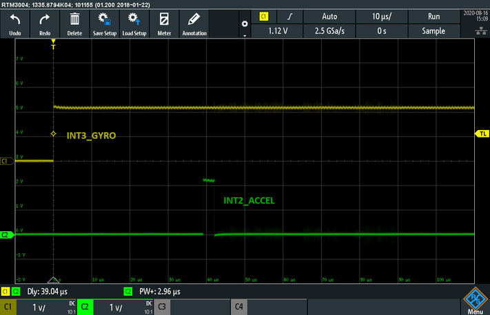
With the above electrical connections implemented, I observe the following timing on the INT2_ACCEL (accelerometer data ready) and INT3_GYRO (gyroscope data ready) pins.
These measurements show the accelerometer data ready interrupt (a 3 us pulse) consistently occurring 39 us after the gyroscope data ready interrupt. These measurements seem to suggest that my implementation and inferred theory of operation for the synchronisation feature is correct.
It is important that our product design is not based on incorrect assumptions. Thank you in advance for taking the time to respond to this detailed post. I hope it will also be of use to others on this forum.
Solved! Go to Solution.
- Mark as New
- Bookmark
- Subscribe
- Mute
- Subscribe to RSS Feed
- Permalink
- Report Inappropriate Content
08-17-2020 11:38 AM
Since this feature is also available for the BMI085 & BMI088 of the same family, there is a bit more details in their respective github repository, and for a little more theoretical background I would refer to this Data Synchronization Application Note.
Your understanding is quite correct, except that the gyroscope interrupt signal cannot be used to directly trigger a physical accelerometer measurement, but instead the accelerometer provides interpolated data based on timestamp difference.
Still looking for something?
- Top Results
