- Top Results
- Bosch Sensortec Community
- Discuss
- MEMS sensors forum
- BNO055 MAG_ID & GYP_ID both read 0x00
BNO055 MAG_ID & GYP_ID both read 0x00
- Subscribe to RSS Feed
- Mark Topic as New
- Mark Topic as Read
- Float this Topic for Current User
- Bookmark
- Subscribe
- Mute
- Printer Friendly Page
- Mark as New
- Bookmark
- Subscribe
- Mute
- Subscribe to RSS Feed
- Permalink
- Report Inappropriate Content
05-13-2022 07:46 PM
I'm just starting to use the BNO055 & setting up the I2C I found that my ID's do not all match the data sheet
0 CHIP_ID = 0xA0. This matches the data sheet
- ACC_ID = 0xFB. This matches the data sheet
- MAG_ID = 0x00. This does NOT match the data sheet value of 0x32
- GYP_ID = 0x00. This does NOT match the data sheet value of 0x0F
- SW_REV_ID_LSB = 0x11. This matches the data sheet
- SW_REV_ID_LSB = 0x03. This matches the data sheet
- SW_REV_ID_LSB = 0x15. This matches the data sheet
These are read out in this order so I don't beleive it's an I2C comms issue
Solved! Go to Solution.
- Mark as New
- Bookmark
- Subscribe
- Mute
- Subscribe to RSS Feed
- Permalink
- Report Inappropriate Content
05-16-2022 07:04 PM
Hi,
Thanks for your inquiry.
Please use logic analyzer to monitor I2C bus when you read those chip ID values. Here is the register dump after BNO055 is powered on. AS it can be seen, those chip ID values match the datasheet. Please also google "Arduino BNO055". You will find a lot of sample codes there.
Thanks.
- Mark as New
- Bookmark
- Subscribe
- Mute
- Subscribe to RSS Feed
- Permalink
- Report Inappropriate Content
05-17-2022 01:57 PM
Thank you for your update. I am using a logic analyser & I can see the ID respsonses
The ID's are read one after the other in the other shown in my post. The first 2 are ok & the last 3 are ok. It's just the MAG & GYRO that are worng (both read 0x00). Could this be a POR issue on my unit where the MAG & GYRO engines are not resetting correctly.
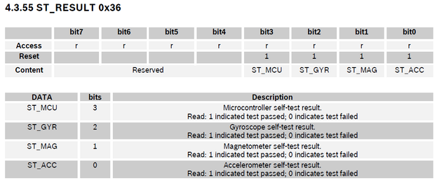
Also when I read the ST_RESULT (0x36) register I get 0x09 instead of 0x0F again implying the MAG & GYRO are not working correctly
Could these units have different code programmed with only the Acceleromoter enabled?
- Mark as New
- Bookmark
- Subscribe
- Mute
- Subscribe to RSS Feed
- Permalink
- Report Inappropriate Content
05-17-2022 04:14 PM
Hi,
Thanks for the verification. If you don't get the default values from BNO055 registers after power on like the register dump in my previous message, then there must be something wrong with the BNO055 chip. Maybe you can check the following:
(1) Are you using BNO055 breakout board or eval. board for testing? Or you have soldered BNO055 chip on your own PCB?
(2) Did you test other BNO055 chips and did they all show the same issue of wrong mag and gyro ID values?
(3) What is the laser marking of the BNO055 chip that you are testing? There should be three rows on the surface of BNO055 chip, for example the laser marking could be 701 A5 194 or 701 A8 1DP, etc.
(4) Where and when did you get the BNO055 chip(s)?
Thanks.
- Mark as New
- Bookmark
- Subscribe
- Mute
- Subscribe to RSS Feed
- Permalink
- Report Inappropriate Content
05-21-2022 07:34 PM
I have the BNO055 mounted on my own board & I've found one of them is faulty. Using my 2nd board & get better results. But I have to slow my I2C bus down. It' quite slow now as I'm only bit banging it with an 8-bit CPU using the GPIO pins. I also only noticed the 600mS POR delay!! so I'm now up & running 🙂
One other thing I found. When selecting the external crystal & found I needed to wait a period of time (I'm waiting 10mS) before checking the clock stats bit otherwise I get a false positive & then reading the system trigger reg reports the external crysal is not test
    // use external clock //
    BNO055_I2C_Write(BNO055_SYS_TRIGGER_ADDR, 0x80);
    Delay(TICK_10MS); // required to avoid false +ve in CLK_STAT

    while(BNO055_I2C_Read(BNO055_SYS_CLK_STAT_ADDR) & 1)
    {
        Delay(TICK_10MS);
    }

    if((BNO055_I2C_Read(BNO055_SYS_TRIGGER_ADDR) & 0x80) == 0)
        while(1);   // !!! EXTERNAL CLOCK SELECTION FAILED
Still looking for something?
- Top Results

