

Hello everyone,
I have a question regarding the BMA400, more specifically the current consumption and electrical behavior of its INTERRUPT outputs, particularly when they are configured as open-drain.
Here is the schematic around the sensor:
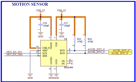
As you can see, I have added 470 kΩ pull-up resistors on the INTx outputs, with VDD_LT = 3.0 VDC.
However, when I measure the voltage levels on these I/Os configured as open-drain, active-low, the high level only reaches approximately 2.0 V.
When I configure the INTx outputs as push-pull, I correctly obtain a signal switching between 0 V and 3.0 V.
Interestingly, when I add a lower-value resistor (approximately 15 kΩ) in parallel with the existing pull-ups, I again obtain the expected 0 V to 3.0 V levels when the INTx outputs are configured as open-drain.
I could not find any information in the sensor datasheet or in the online knowledge base indicating the maximum recommended pull-up resistance for the INTx outputs depending on the supply voltage.
Could someone help me understand this behavior and advise on the appropriate pull-up resistance for the INTx outputs at VDD_LT = 3.0 V?
Thanks in advance for your help!